- Google Nest Community
- Thermostats
- Wire configuration from Honeywell thermostat to Go...
- Subscribe to RSS Feed
- Mark Topic as New
- Mark Topic as Read
- Float this Topic for Current User
- Bookmark
- Subscribe
- Mute
- Printer Friendly Page
Wire configuration from Honeywell thermostat to Google Nest thermostat?
- Mark as New
- Bookmark
- Subscribe
- Mute
- Subscribe to RSS Feed
- Permalink
- Report Inappropriate Content
09-22-2023 01:05 PM
Hey all, have a Google Nest thermostat to install, replacing a Honeywell.
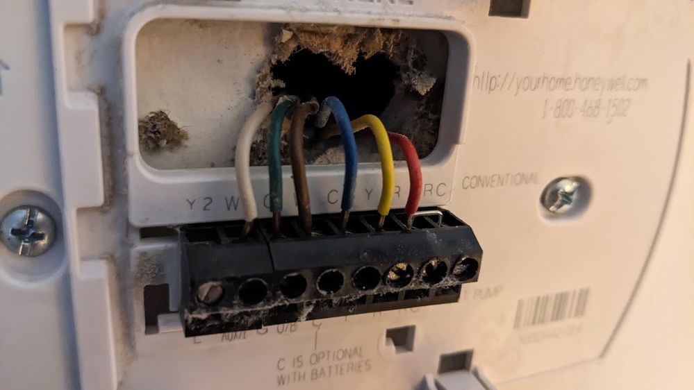
There are 6 wires in the Honeywell config currently
W2 - white wire
G - Green
W - Brown
C - Blue
Y - Yellow
R - Red
Images of the Honeywell setup:
Can someone tell me which wire plugs into each port on the Nest?
I am assuming all the current wires with identical ports are the same, however the Brown/W and White/W2 on the Honeywell are throwing me off a bit.
Thanks in advance for all assistance.
- Mark as New
- Bookmark
- Subscribe
- Mute
- Subscribe to RSS Feed
- Permalink
- Report Inappropriate Content
09-25-2023 03:11 PM
Hello jeckr1,
Thanks for posting here in the Community. Just to verify: Do you know if your HVAC system is a heat pump or a conventional system? If not, please give us the make and model of your HVAC so that we can determine the correct wiring configuration on the Nest Thermostat.
I look forward to your response.
Best,
Edmond
- Mark as New
- Bookmark
- Subscribe
- Mute
- Subscribe to RSS Feed
- Permalink
- Report Inappropriate Content
10-04-2023 11:11 AM
- Mark as New
- Bookmark
- Subscribe
- Mute
- Subscribe to RSS Feed
- Permalink
- Report Inappropriate Content
10-04-2023 02:05 PM
Hi folks,
@Jeckr1, thanks for providing the photos above. Upon checking, your system is a heat pump and it has 208-230 V. This amount of voltage isn't compatible with the Nest Thermostats, as it is considered high voltage. For the system to be compatible, it should only deliver 24-30 V to the thermostat.
I'd like to take a closer look at it. Do you have a voltmeter? If yes, are you comfortable using it?
Voltmeters and multimeters come in two types, analog and digital. Analog models are no longer common, but they can still be found. They have a needle that moves across a window similar to a speedometer on a car. Digital models give a specific readout of the exact voltage measured. They can be extremely accurate and helpful for measuring voltage.
When using a voltmeter you should turn the dial or switch to AC. AC current allows voltage to flow through the leads and allows the voltmeter to display an accurate readout. To check voltage over any R wire: If your breakers are off, you will need to turn them on. On most multimeters, AC current is designated by VAC or V~.
Please follow the guide below to check the amount of power running through the wires:
- Set the dial to 200 VAC.
- If the multimeter doesn’t have a 200 setting, choose 100 or 250 VAC.
- The general rule of thumb is don’t set it too high (500+) or too low (50).Place the red lead on the R wire.
- Place the black lead on the other wire being tested (W1, Y1 or C).
- The normal readout should be somewhere between 20 and 30 V (24 V is most common).
I appreciate the input, Edmond.
Regards,
Jenelyn


